
Introduction to Injection Molding Tolerances
In the world of manufacturing, perfection is a theoretical concept, not a practical reality. No two parts produced—whether machined, cast, or molded—are ever identical down to the atomic level. In injection molding, where molten plastic is subjected to intense heat, pressure, and cooling, variables are everywhere.
For engineers and product designers, the challenge isn’t to eliminate these variations, but to control them. This is where injection molding tolerances come into play. Understanding how to define, measure, and design for these tolerances is the difference between a high-performance assembly and a costly manufacturing failure.
This guide will walk you through the complexities of injection molding tolerances, from industry standards like ISO 20457 to the practical “steel safe” design strategies used by veteran molders.
What are Injection Molding Tolerances?
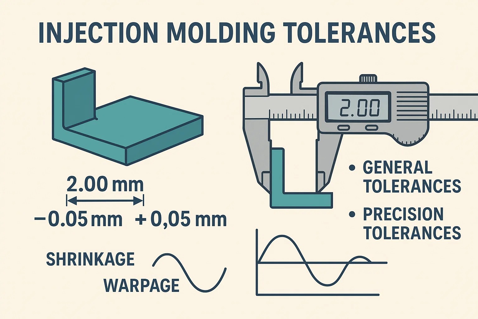
In simplest terms, a tolerance is the allowable variation in a specific dimension of a molded part. It is the range of deviation—plus or minus—from the nominal design value that a part can have while still functioning correctly.
For example, if a design calls for a wall thickness of 2.00 mm with a tolerance of ± 0.05 mm, any part measuring between 1.95 mm and 2.05 mm is acceptable.
However, injection molding tolerances are unique compared to metalworking. Unlike CNC machining, where a cutting tool progressively removes material to hit a dimension, injection molding relies on the material shrinking as it cools.
- Shrinkage: All plastics shrink as they transition from liquid to solid.
- Warpage: Different areas of a part often cool at different rates, leading to internal stresses.
Because of this, tolerances in injection molding are classified into two general categories:
- General (Commercial) Tolerances: These are wider standard tolerances suitable for most features where high precision is not critical. They are cost-effective and easier to achieve.
- Fine (Precision) Tolerances: These are tighter ranges reserved for critical features (like bearing fits or sealing surfaces). They require specialized mold construction, premium materials, and strict process control—all of which increase cost.
Why are Tolerances Important in Injection Molding?
Tolerances are not just numbers on a print; they are the contract between the designer and the manufacturer. Establishing clear, realistic tolerances is critical for three main reasons:
1. Assembly Fit and Function
Most injection molded parts are components of a larger system. If tolerances are too loose, parts may rattle, leak, or fail to snap together. If tolerances are too tight on non-critical features, you may reject perfectly functional parts.
- Example: A snap-fit enclosure requires precise tolerances on the clip mechanism to function, but loose tolerances on the external textured surface are acceptable.
2. Manufacturing Cost Control
There is a direct exponential relationship between tolerance tightness and part cost.
- Looser Tolerances: Allow for faster cycle times, standard tooling, and cheaper materials (like commodity Polypropylene).
- Tighter Tolerances: Require slower processing (to ensure uniform cooling), high-precision steel molds, and expensive engineering resins (like Glass-Filled Nylon or PEEK).
- The Golden Rule: “Design for the loosest tolerance that still allows the part to function.”
3. Consistency and Repeatability
Tolerances provide a benchmark for quality control. They allow manufacturers to validate that their process is stable. If parts start drifting out of tolerance, it signals that process parameters—like injection pressure or cooling time—have shifted and need correction.
Factors Affecting Injection Molding Tolerances
Achieving precision in injection molding is a balancing act. Unlike machining, where the tool path dictates the final dimension, molding involves a phase change—liquid to solid—that inherently introduces movement and variability.
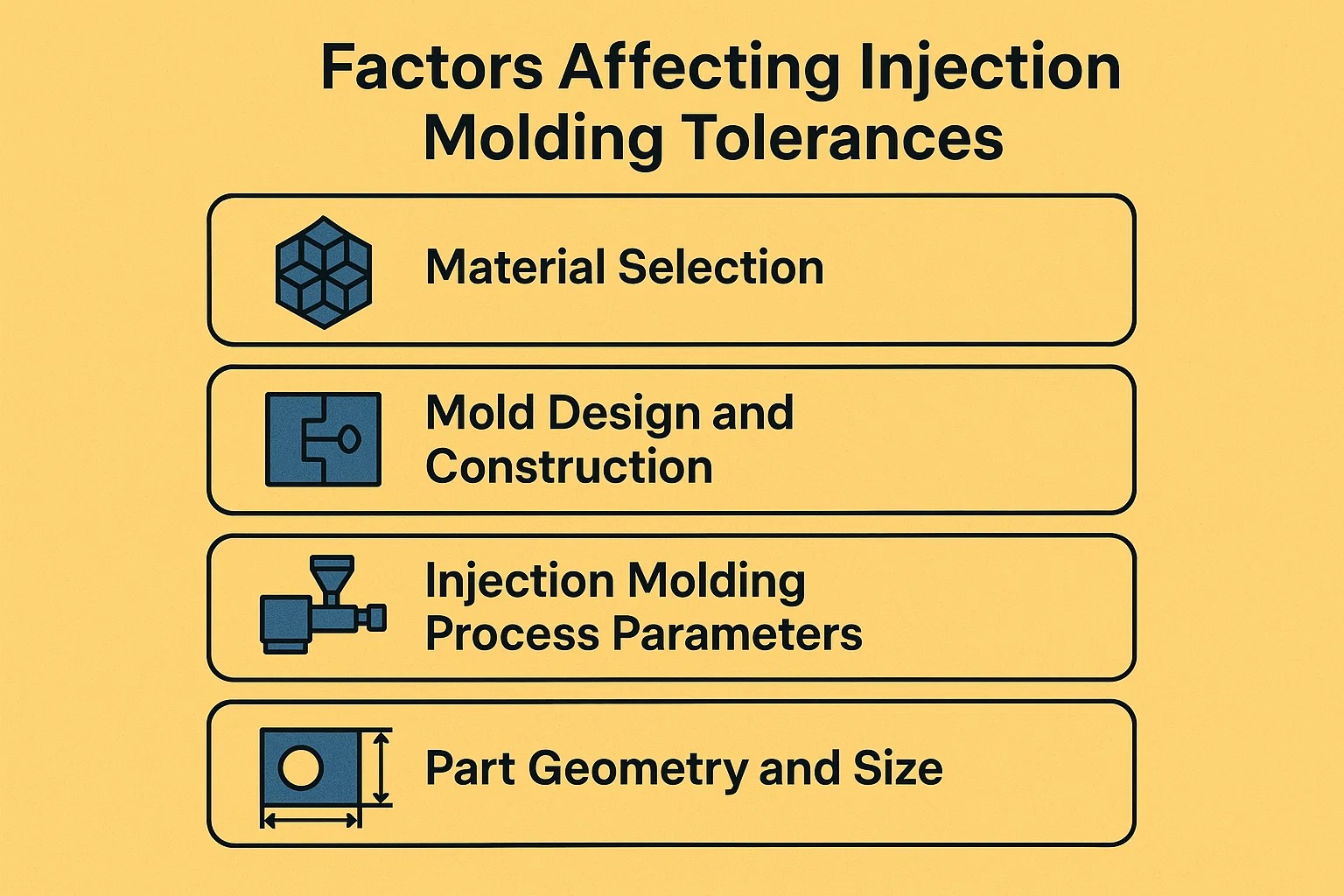
Four primary factors influence whether a part will hit its tolerance targets or end up in the scrap bin.
1. Material Selection: The Foundation of Tolerance
The choice of resin is the single biggest predictor of achievable tolerances. Plastic materials behave differently as they cool and solidify, primarily due to their molecular structure.
-
Shrinkage Rates:
- Amorphous Plastics (e.g., ABS, Polycarbonate, Polystyrene): These materials cool gradually and shrink less (typically 0.4% – 0.8%). They generally hold tighter tolerances .
- Semi-Crystalline Plastics (e.g., Polypropylene, Nylon, Polyethylene): These undergo a rapid crystallization phase when cooling, leading to significant volume change. They shrink more (typically 1.0% – 2.5% or more) and are harder to hold to tight tolerances.
-
The Role of Fillers:
Adding fillers like Glass Fiber or Mineral Fillers significantly improves dimensional stability. The fibers mechanically restrict shrinkage, allowing materials like Nylon to hold much tighter tolerances than they would in their unreinforced state.- Caveat: Fibers tend to align with the flow of plastic, causing anisotropic shrinkage —meaning the part shrinks differently in the direction of flow versus across the flow.
2. Mold Design and Construction
You cannot mold a precision part from an imprecise tool. The quality of the mold directly correlates to the quality of the final part.
- Tooling Precision: A high-precision steel mold (Class 101) is CNC machined and EDM eroded to tolerances often within ± 0.005 mm. Aluminum or soft tooling cannot hold these same ranges over time.
- Cavitation:
- Single-Cavity Molds: Offer the highest precision because every shot is identical.
- Multi-Cavity Molds: Introduce “cavity-to-cavity” variation. Even with perfect machining, subtle flow imbalances can cause Cavity 1 to produce parts slightly larger than Cavity 4.
- Gate Location: The gate is where plastic enters the mold. Plastic shrinks more in the direction of flow than perpendicular to it. A poor gate location can cause ovality in circular parts or warping in long, flat parts.
- Cooling System: Uniform cooling is critical. If one side of the mold is hotter than the other, the part will shrink unevenly and warp (bow) towards the hotter side.
3. Injection Molding Process Parameters
Even with the perfect material and a perfect mold, the machine settings (process window) can alter dimensions.
- Injection Pressure & Packing: “Packing” refers to adding more material into the mold as the part cools to compensate for shrinkage.
- High Pack Pressure: Forces more plastic in, reducing shrinkage (part is larger).
- Low Pack Pressure: Allows more shrinkage (part is smaller).
- Melt and Mold Temperature: Higher temperatures generally allow for better flow but extend cooling times. If a part is ejected while still too hot, it may continue to shrink or warp outside the mold.
4. Part Geometry and Size
The design of the part itself imposes physical limits on tolerances.
- Overall Size: Tolerance is often a function of size. It is exponentially harder to hold ± 0.1 mm on a 500mm automotive dashboard than on a 10mm gear.
- Wall Thickness Consistency: This is the golden rule of plastic design.
- Uniform Walls: Result in uniform cooling and predictable shrinkage.
- Variable Walls: Thick areas cool slower than thin areas, creating internal stresses that pull the part out of shape (warpage), destroying dimensional accuracy.
Summary Table: Factors at a Glance
| Factor | Enhances Tolerance Control (Easier) | Reduces Tolerance Control (Harder) |
|---|---|---|
| Material | Low-shrink (ABS, PC), Glass-filled | High-shrink (PP, HDPE), Unfilled |
| Mold | Single-cavity, Precision Steel, Conformal Cooling | Multi-cavity, Aluminum, Poor Cooling |
| Geometry | Small size, Uniform wall thickness | Large size, Variable walls, Flat unsupported surfaces |
Standard Tolerances and Guidelines
Since “perfect” dimensions are impossible, the industry relies on established standards to define what is acceptable. These standards provide a common language for engineers and molders to agree on quality expectations before a mold is ever cut.
1. Industry Standards for Injection Molding
While many companies create their own internal tolerance sheets, there are recognized international standards that serve as the baseline for the industry.
-
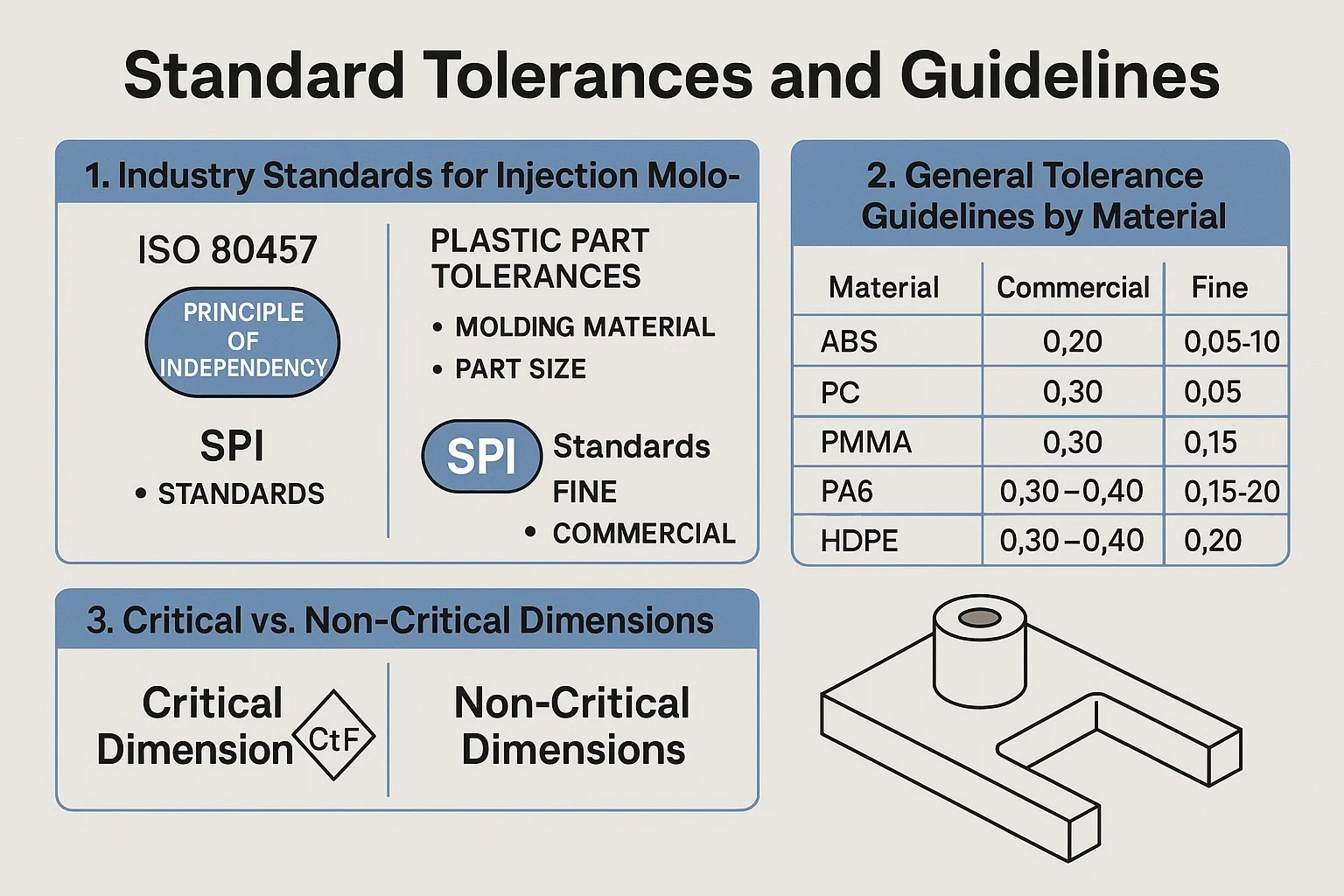
ISO 20457 (formerly DIN 16901):
This is currently the most significant global standard for plastic part tolerances. It replaced the widely used DIN 16901. ISO 20457 classifies tolerances based on two main variables:- Molding Material: Materials are grouped by their shrinkage characteristics.
- Part Size: Larger dimensions inevitably have larger allowable deviations.
-
ISO 8015 (Fundamental Tolerancing):
This standard establishes the “Principle of Independency.” It states that each specified dimensional and geometric requirement (like flatness or roundness) must be met independently unless a specific relationship is defined (e.g., via GD&T modifiers). -
SPI Standards (Society of the Plastics Industry):
Common in the United States, SPI standards simplify expectations by offering two primary classes:- “Fine” (Precision): Tighter controls, higher cost.
- “Commercial” (General): Standard controls, lower cost.
2. General Tolerance Guidelines by Material
The table below provides a practical reference for linear tolerances (±mm) based on typical industry capabilities. Notice the distinct difference between amorphous resins (like ABS) and semi-crystalline resins (like PP).
| Material | Shrinkage | Commercial Tolerance (±mm) | Fine Tolerance (± mm) |
|---|---|---|---|
| ABS | Low | $0.20$ | $0.05 - 0.10$ |
| Polycarbonate (PC) | Low | $0.20$ | $0.05 - 0.10$ |
| Acrylic (PMMA) | Low | $0.20$ | $0.05 - 0.10$ |
| Nylon (PA6) | High | $0.30$ | $0.15$ |
| Polypropylene (PP) | High | $0.30 - 0.40$ | $0.15 - 0.20$ |
| Polyethylene (HDPE) | High | $0.30 - 0.40$ | $0.20$ |
| TPU / Rubber | Very High | $0.50$ | $0.25$ |
Note: These values are estimates for small-to-medium features (e.g., 25mm to 50mm). As parts get larger, these tolerance bands must widen.
3. Critical vs. Non-Critical Dimensions
One of the most common mistakes in part design is applying a “blanket tolerance” (e.g., “All tolerances ± 0.1 mm”) to the entire drawing. This drives up mold costs unnecessarily.
Effective tolerancing splits dimensions into two categories:
-
Critical Dimensions (CtF - Critical to Function):
These are features that interact with other parts—snap fits, bearing holes, or sealing surfaces. These require Fine Tolerances . You must identify these explicitly on the 2D drawing (often marked with a symbol like a diamond or oval). -
Non-Critical / Reference Dimensions:
These are aesthetic surfaces, ribs, or outer contours that do not touch other components. These should use Commercial Tolerances . Loosening these tolerances allows the molder to focus their process control on the few dimensions that actually matter.
Designing for Tolerances
The battle for tight tolerances is often won or lost on the designer’s CAD screen, long before the mold is cut. A design that fights the injection molding process will never hold consistent dimensions, no matter how precise the mold is.
Here are the best practices for designing parts that naturally hold their tolerances.
1. The “Steel Safe” (Metal Safe) Strategy
This is the most critical concept for managing tolerances in a new mold.
Because plastic shrinkage is an estimate, not a guarantee, you should never cut the mold to the exact nominal dimension immediately. Instead, design the mold so that you can remove metal later to dial in the tolerance. It is easy to remove metal from a mold (grinding/EDM), but very difficult and expensive to add it back (welding).
- For Holes (Cores): Design the metal pin in the mold slightly larger . This makes the plastic hole smaller . If the hole is too tight, you can machine the pin down to open up the hole.
- For Outer Walls (Cavities): Cut the metal cavity slightly smaller . This makes the plastic part smaller . If the part is too small, you can grind the cavity walls to make the part bigger.
2. Draft Angles and Dimensional Measurement
Draft angles (tapers) are mandatory to allow the part to eject from the mold without dragging. However, draft complicates tolerances because a tapered wall does not have a single dimension—it changes from the bottom to the top.
- The Conflict: If you specify a width of 20 mm ± 0.1, but the wall has a 2° draft, the width might be 20.0 mm at the bottom and 20.5 mm at the top.
- The Solution: You must specify where the tolerance applies.
- “Measure at Major Diameter”: Usually the widest point.
- “Measure at Root”: The base of the feature.
- Typically, you need at least 0.5° to 1° of draft for standard features, and 3° or more for textured surfaces.
3. Ribs, Bosses, and Sink Marks
Features like ribs (for strength) and bosses (for screw insertion) are common sources of tolerance failure—specifically “profile” or “flatness” failures.
If a rib is too thick where it meets the main wall, it retains heat. As that thick intersection cools, it pulls the outer surface inward, creating a Sink Mark (a depression).
- Tolerance Impact: A sink mark ruins the flatness tolerance of the surface.
- The Rule: The thickness of a rib should be no more than 60% of the nominal wall thickness.
4. GD&T: Beyond Linear Tolerances
For complex parts, simple linear tolerances (±mm) are often insufficient. Plastic parts are flexible and prone to warping, meaning they might be the correct size but the wrong shape .
- Flatness: Critical for sealing surfaces. Because plastics warp, achieving a flatness of 0.05 mm over a large area is extremely difficult.
- Concentricity: Critical for gears or rotating parts.
- Positional Tolerance: Ensures that a screw boss is in the right location relative to the alignment pins, which is more useful than measuring the distance from the edge of the part.
Pro Tip: Avoid specifying tight flatness tolerances on large, unsupported plastic surfaces. If you need a flat surface, add structural ribs underneath to stiffen it against warpage.
Common Injection Molding Defects Related to Tolerances
When a part fails to meet tolerance, it is rarely because the machine just “guessed wrong.” Tolerance failures are almost always the result of specific, identifiable molding defects. Understanding these defects is the key to troubleshooting dimensional issues.
1. Warpage (The “Potato Chip” Effect)
Warpage is the most common enemy of Geometric Dimensioning and Tolerancing (GD&T) , specifically Flatness and Profile.
- The Cause: Warpage happens when different parts of the molded component shrink at different rates. This is usually caused by:
- Non-uniform wall thickness: Thick sections stay hot longer than thin sections.
- Uneven cooling: If one half of the mold is 40 °C and the other is 60 °C , the part will bow toward the hotter side as it cools.
- Tolerance Impact: A part might have the correct length and width, but if it is bowed by 2 mm, it will not mate with a flat surface. This makes holding tight flatness tolerances (e.g., 0.1 mm) extremely difficult for large, flat parts.
2. Unpredictable Shrinkage
Every plastic shrinks, but variation in shrinkage is what kills tolerances.
- The Cause: Shrinkage is driven by the density of the packed plastic. If the “holding pressure” (packing phase) varies from shot to shot, or if the gate freezes off too early on some cycles, the amount of plastic in the mold cavity changes.
- Tolerance Impact: This leads to linear dimension failures. One part might be 100.0 mm (perfect), and the next might be 99.8 mm because the pack pressure dropped slightly.
- Anisotropy: Fiber-filled materials (like Glass-Filled Nylon) shrink much less in the direction of flow than they do cross-flow. If the mold designer didn’t account for this directionality, the part will be oval instead of round.
3. Sink Marks
A sink mark is a small depression or dimple on the surface of a part.
- The Cause: It occurs when the outer skin of the part cools and solidifies, but the inner core remains molten. As the inner core cools and shrinks, it pulls the outer skin inward. This happens most often at thick intersections, such as where a rib or boss meets a wall.
- Tolerance Impact: While often considered a cosmetic defect, sink marks are a tolerance disaster for sealing surfaces. If an O-ring groove has a sink mark, the depth of the groove changes locally, causing a leak path.
4. Dimensional Instability (Post-Molding)
Sometimes, the part is perfect when it leaves the factory but fails tolerance when it arrives at the customer.
- Hygroscopic Materials: Plastics like Nylon (PA) absorb moisture from the air. As they absorb water, they swell. A dry Nylon part might grow by 0.5% to 1.0% after being exposed to humidity for a few weeks.
- Thermal Expansion: Plastics have a high Coefficient of Thermal Expansion (CTE). A tolerance check performed in a cold warehouse may yield different results than one performed in a hot assembly plant.
- Stress Relaxation: If a part is ejected with high internal stress (due to fast cooling), it may slowly warp over the course of 24-48 hours as the molecules relax into their natural state.
Optimizing the Injection Molding Process for Tight Tolerances
Achieving tight tolerances is not just about building a precise mold; it is about establishing a stable, repeatable process. If the manufacturing conditions fluctuate—even slightly—the dimensions of the parts will drift.
Here is how top-tier molders optimize the process to hold precision tolerances.
1. Scientific Molding (Decoupled Molding)
The “old school” way of molding involved filling the mold as fast as possible until it was full, often relying on one continuous pressure setting. This is inconsistent.
Modern precision molders use Scientific Molding (often called Decoupled Molding). This technique separates the molding process into two distinct stages to gain maximum control:
- Stage 1 (Velocity Control): The mold is filled to about 95-98% capacity using speed (velocity) control. This is done quickly to ensure the material doesn’t freeze prematurely.
- Stage 2 (Pressure Control): The machine switches to pressure control to “pack” the final 2-5% of the cavity. This packing phase compensates for shrinkage.
Why this helps tolerances: By decoupling these stages, the molder can precisely control exactly how much plastic is packed into the mold on every single shot, eliminating density variations that cause size fluctuation.
2. Material Handling and Drying
You cannot mold precision parts with wet material.
Many engineering resins (Nylon, PC, PET, ABS) are hygroscopic , meaning they absorb moisture from the air. If wet plastic is melted, the water turns to steam, creating voids and degrading the plastic’s molecular chains.
- The Result: The plastic becomes less viscous (runnier), causing the mold to over-pack or flash, altering dimensions.
- The Fix: Precision molders use Desiccant Dryers to remove moisture to a specific dew point (e.g., -40°C) before the material ever enters the machine.
3. Advanced Process Controls
For “Fine” or “Precision” tolerance classes, standard machine controls may not be enough. Advanced technologies are used to monitor the environment inside the mold itself.
-
In-Mold Cavity Pressure Sensors:
Instead of trusting the machine’s pressure gauge (which is far away from the mold), sensors are placed directly inside the mold cavity. They tell the machine exactly when the mold is full and when to switch from Fill to Pack. This allows the machine to adjust itself in real-time if the material viscosity changes slightly. -
Conformal Cooling:
Standard molds use straight drilled water lines for cooling, which can leave “hot spots” in complex areas. Conformal cooling uses 3D-printed metal inserts to create cooling channels that curve and twist to follow the exact shape of the part.- Benefit: This ensures every millimeter of the part cools at the exact same rate, virtually eliminating warpage and locking in tight tolerances.
4. Tooling Maintenance and Calibration
A mold is a moving machine that wears out over time.
- Vent Cleaning: As air escapes the mold, it leaves behind residue in the vents. If vents clog, air gets trapped, creating back-pressure that prevents the plastic from filling the detail fully. This leads to “short shots” (undersized parts).
- Parting Line Wear: Over thousands of cycles, the steel edges that seal the mold can wear down, leading to “flash” (excess plastic seeping out). Flash adds thickness to the part, throwing off dimensions across the parting line.
Measuring and Verifying Tolerances
Producing a part is only half the battle; proving that it meets the engineering specifications is the other half. In high-precision industries like medical and automotive, “it looks good” is not a valid quality criteria.
Manufacturers use a tiered approach to metrology (measurement) depending on the tolerance class and the feature type.
1. Coordinate Measuring Machines (CMMs)
The CMM is the gold standard for verifying injection molded tolerances. It uses a highly sensitive touch probe to physically tap specific points on the part’s surface, mapping them in 3D space.
- Best For: Critical dimensions with tight tolerances (e.g., ± 0.05 mm), hole diameters, and geometric tolerances like flatness or parallelism.
- The Limitation: Because it uses a physical probe, it can be slow. Also, for very soft materials (like TPE or rubber), the pressure of the probe itself might deform the part, causing inaccurate readings.
2. Optical and Vision Measurement Systems
For parts that are too small, too flexible, or too complex for a touch probe, optical systems are used. These systems use high-resolution cameras and edge-detection software to measure dimensions without physically touching the part.
- Best For:
- Soft/Flexible Parts: Measuring a rubber seal without deforming it.
- Small Details: Micro-molding features invisible to the naked eye.
- Speed: Instantaneously measuring multiple dimensions in a single “snapshot” (e.g., checking all 4 hole locations at once).
3. Computed Tomography (CT) Scanning
This is the cutting-edge of injection molding metrology. CT scanning uses X-rays to create a complete 3D model of the part—both inside and out.
- Why it is a Game Changer:
- Internal Verification: It is the only non-destructive way to measure internal features, such as the wall thickness of a hollow part or the internal threads of a medical luer connector.
- Defect Detection: It can see inside the plastic to detect hidden voids (air bubbles) that weaken the part, even if the exterior dimensions are perfect.
- Part-to-CAD Overlay: The software overlays the scanned 3D model directly onto the original CAD file, creating a color map (heatmap) that instantly shows where the part is too big (red) or too small (blue).
4. Functional Gauging (Go / No-Go Fixtures)
While CMMs provide data, sometimes you just need to know: “Does it fit?”
For high-volume production, molders often build custom Check Fixtures . These are precision-machined metal blocks or stands that mimic the mating part.
- Go/No-Go: If the part fits into the fixture, it passes. If it doesn’t, it fails.
- Speed: This allows operators to check 100% of parts on the production line immediately after they eject from the machine, ensuring that a process drift is caught instantly.
Cost Considerations and Tolerance Selection
There is a fundamental rule in manufacturing: Precision costs money.
Understanding the relationship between tolerance tightness and production cost is vital for project managers and designers. A common mistake is applying a blanket “tight tolerance” to an entire drawing, which can unnecessarily double or triple the cost of a mold.
1. The Relationship Between Tolerance and Cost
The cost of achieving a tolerance is not linear; it is exponential .
- Commercial Tolerances (± 0.1 mm - ± 0.3 mm): These are achieved with standard CNC machining and standard molding cycles. This represents the baseline cost.
- Precision Tolerances (± 0.05 mm): To hold this range, the mold maker must use slower EDM (Electrical Discharge Machining) processes, higher-grade steel, and the molder must run slower cycle times to ensure thermal stability.
- Ultra-Precision (± 0.01 mm): This requires specialized micro-molding equipment, climate-controlled inspection rooms, and 100% part inspection. The cost can be 5x to 10x the baseline.
2. Balancing Precision and Cost-Effectiveness
To optimize the budget without sacrificing quality, use a “Risk-Based Tolerancing” strategy:
- Identify Critical Features (CtF): Assign tight tolerances only to the features that matter—snap fits, bearing bores, and sealing surfaces.
- Loosen the Rest: For non-critical features like ribs, outer wall thickness, or decorative surfaces, use standard commercial tolerances. This gives the molder a wider “process window” to produce good parts efficiently.
Case Studies: Real-World Examples
To see these principles in action, let’s look at how different industries approach tolerances.
Medical Devices (High Precision)
- Application: A dosage adjustment dial on an insulin pen.
- Tolerance Strategy: Requires extremely tight tolerances (± 0.02 mm) on the internal gear teeth to ensure the correct drug dose is delivered.
- Trade-off: High mold cost and slower cycle times are accepted because patient safety is the priority. Materials like PEEK or Polycarbonate are used for stability.
Automotive Components (Mixed Precision)
- Application: A car door interior panel.
- Tolerance Strategy:
- Mounting Clips: Tight tolerance to ensure the panel snaps onto the metal frame without rattling.
- Surface Contour: Looser tolerance on the large plastic curves. The flexibility of the material allows it to conform to the car body.
- Trade-off: Focus is on “fit and finish” rather than micron-level accuracy.
Consumer Electronics (Cosmetic Focus)
- Application: A TV remote control housing.
- Tolerance Strategy: The most critical tolerance is the parting line fit between the top and bottom halves. If the tolerance is off, the user feels a sharp edge.
- Trade-off: Engineers focus on “gap and flush” tolerances rather than internal dimensional precision.
Conclusion
Key Takeaways on Injection Molding Tolerances
Injection molding is a complex dance of heat, pressure, and material science. While “perfect” dimensions are theoretically impossible, predictable dimensions are achievable with the right approach.
- Material Dictates Potential: You cannot hold the same tolerance on Polypropylene (high shrink) as you can on Polycarbonate (low shrink).
- Design “Steel Safe”: Always design the mold to allow for metal removal. It is the cheapest insurance policy against tolerance failures.
- Process Control is King: A precise mold is useless without a stable process. Techniques like Decoupled Molding and Scientific Molding are essential for consistency.
- Communicate Early: The most successful projects involve the molder during the design phase. They can spot a tolerance issue on a CAD model long before steel is cut.
Future Trends in Precision Manufacturing
As industries like Micro-Fluidics and Wearable Tech grow, the demand for precision is pushing the boundaries of what is possible.
- Smart Molds: Molds equipped with AI-driven sensors that auto-adjust injection pressure in real-time to compensate for material variations.
- Micro-Molding: The ability to mold parts smaller than a grain of rice with tolerances in the single-digit microns (± 0.005 mm).
By understanding the limits and capabilities of the injection molding process, engineers can design parts that are not only manufacturable but functional, cost-effective, and high-quality.
Frequently Asked Questions (FAQ)
1. What is the standard tolerance for injection molding?
There is no single “standard,” but the industry baseline for general commercial tolerances is typically ± 0.1 mm to ± 0.25 mm for small-to-medium parts. For high-precision parts, tolerances can be tightened to ± 0.05 mm , though this increases cost significantly.
2. Which plastic material holds the tightest tolerances?
Amorphous resins with low shrinkage rates hold the best tolerances.
- Best: Liquid Crystal Polymer (LCP) , Polycarbonate (PC) , ABS , and PEEK .
- Better with Fillers: Adding Glass Fiber or Carbon Fiber to any material (even Nylon or PP) significantly reduces shrinkage and improves tolerance control.
3. Why is my injection molded part smaller than the design?
This is likely due to shrinkage . All plastics shrink as they cool. If the mold designer did not accurately calculate the “shrink rate” of your specific material and scale the mold up to compensate, the final part will be undersized. It can also be caused by low packing pressure during the molding process.
4. Can I achieve “Zero Tolerance” in plastic parts?
No. “Zero tolerance” is physically impossible in any manufacturing process, especially with plastic. Plastic is sensitive to temperature and moisture; a part measured in a cold room will be different from one measured in a hot room. You must always define an acceptable range (e.g., ± 0.02 mm).
5. How do I fix a warped part that is out of tolerance?
Warpage is usually caused by uneven cooling.
- Design Fix: Ensure wall thickness is uniform . Coring out thick sections can help.
- Process Fix: Adjust the cooling time or ensure the mold temperature is consistent on both the cavity and core sides.
- Tooling Fix: Add Conformal Cooling channels to the mold to target hot spots.
6. What is the difference between ISO 2768 and ISO 20457?
- ISO 2768 is a general tolerance standard primarily intended for machined metal parts . It is often incorrectly applied to plastics.
- ISO 20457 (formerly DIN 16901) is the specific standard for injection molded plastic parts , accounting for molding variables like shrinkage and elasticity. You should always reference ISO 20457 for plastic components.
7. Does wall thickness affect tolerance?
Yes, significantly. Thicker walls shrink more and are prone to sink marks and voids . Inconsistent wall thickness causes warpage . Keeping walls uniform and relatively thin (typically 2mm - 3mm) is the best way to ensure consistent dimensions.

